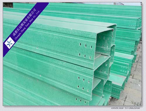
Cable Tray
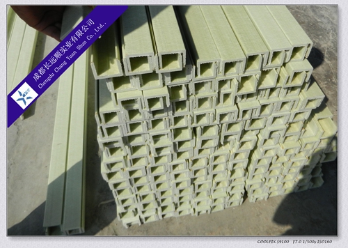
Cable tray is assembled by pultruded FRP profiles; suitable for electrical cable, control cables, lightening cable and fittings.

characteristics:
1. Long service life (normal design life is 20 years).
2. Convenient installation, and low cost (1/4 SG of carbon steel, no need of fire during construction; length per piece can be 8 m, or more.)
3. Easy to cut, no need of maintenance
Application:
CYS cable tray is suitable for voltage below 10 kV electrical cables, control cable, and lightening fitting cables of below 10 kV and the lay out for indoor, outdoor, aerial, channel for cable and tunnel.
Structural features:
CYS cable trays have the features that: widely used, high strength, reasonable structure, low cost, easy for construction, flexible fittings, nice-looking appearance, which make expansion, rebuilding, maintenance much easier.
Installation:
The installation of CYS cable tray can be per the local conditions can be laid according to the process requirements, such as plumbing, floor, hoisting under the beam, indoor and outdoor wall, tunnel, cable trench side wall mounted, but also on the open column.
1. When height of groove of cable tray is 50,100 mm, 6 connection holes for each end; when height of groove of cable tray is 150,200 mm, 12 connection holes for each end.
2. Support Spacing: it shall be less than or equal load curve, allowable load and support span.
3. Width: when we are electing the width of cable tray, we should leave enough spare space for new cables in the future.
4. Separated lying: when there are less power cables and control cables, they can be installed in the same cable tray, but there should be a separation plate between the power cable and control cable.
5. Fixing of cables: when the cable trays are horizontal laid, the connection point shall be in the position of 1 / 4, horizontal cable shall be fixed every 2 meters, the vertical cable trays shall be fixed every 1.5 meters.
Laying method:
Weak current control cables shall be at the top layer, general control cables and low voltage power cable are downward arrangement. This kind of arrangement is good for shielding; good for cooling and site construction.
Distance between cable trays:
1. To ensure easy installation, cable tray and the spacing must satisfy the following data:
A. When we are setting cable trays in the same support beam or in the same horizontal level, the net distance between adjacent cables trays should not be less than 50mm.
B. For two parallel cable tries, its net distance should not be less than 600mm.
2. When the cable trays are overlapped laid, the vertical distance shall meet the following data:
A. For power cable, it should be 300mm.
B. The control cable, it should be 250mm.
3. For the convenience of cable tray installation, the distance between cable tray and the top of the ceiling, beams and other obstacles at the bottom should meet the following data:
A. For power cable, it should be not less than 400mm.
B. For control cable, it should be not less than 250mm.

Notes:
1. Vertical cable trays must be protected by cover on the area which is within two meters above the ground.
2. The position which is liable to mechanical damage must be protected by covers.
3. When the cable trays are horizontally laid, the selection of stride support shall be per the load curve; when the cable trays are vertically laid, there should be a fixing frame every 1 or 2 meters to make sure the stability of the cable trays.
4. When the cables in the cable tray are lead from horizontal direction to vertical direction, there must be a guide plate to protect the cable from damage.
5. When the material of cable tray is steel, there should be a reliable grounding wire; cable trays must be connected with the main grounding wire.
6. In corrosive circumference, 12*4 aluminum sheets or 12*4 belt steel must be laid along the edge of cable trays to service as the grounding wire when it is non-steel cable tray.
7. Cable trays are not allowed to service as the passage way and platform for people.
|
